Height: 125mm
Weight: 110g
Symbol height: 50mm
Ignition voltage (max): 140 V
Maintaining voltage (typical): 132 V
Extinguishing voltage (typical): 120 V
Minimum supply voltage: 170 V
Minimum current: 4.5 mA
Maximum current: 6.5 mA
Storage temperature: from -20ºC to +60ºC
Operating temperature: from -10ºC to + 50ºC
Expected lifetime: over 20 years or 200.000 hours (running 24/7)
Dalibor Farny
Nixie Tubes
https://docs.daliborfarny.com/v2/de/nixie-tubes/
Diese Anleitung gibt es noch nicht in Ihrer Sprache – Teile werden angezeigt auf: English.
R Nixie tube
Technical data
Tube socket
The R|Z568M nixie tube can be connected to the electronic driver in several ways – there are original bakelite sockets from the 70s or you can design your own socket using available pin sockets. The original sockets can be sometimes found on eBay, search for “z568m socket”, the photo below was taken from Z568M Socket by “lci_electronics” seller. A better way is usually to integrate the pin sockets straight into your PCB.
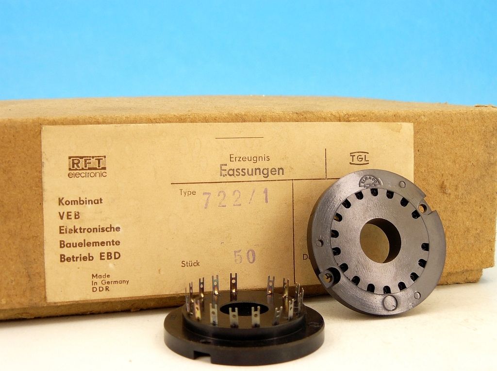
We use Harwin H3161 pin sockets for this purpose. They are well made, quite a low cost, and provide excellent support for the tube. Withdrawal force for the single pin is 1N, which makes 11N for the whole tube (1.1 Kg) – far enough to hold the tube firmly in position even upside down. I use 1.95mm drill bit size for mounting holes in PCB made with ENIG surface finish (gold plating over nickel layer) and 2.00mm for boards made with HAL/HASL surface finish. Both surface finishes make the final hole smaller, HAL/HASL layer is thicker, so a bigger drill bit is necessary. The pin sockets are simply pressed into the holes and soldered from the bottom side.
R|Z568M Nixie tube footprint
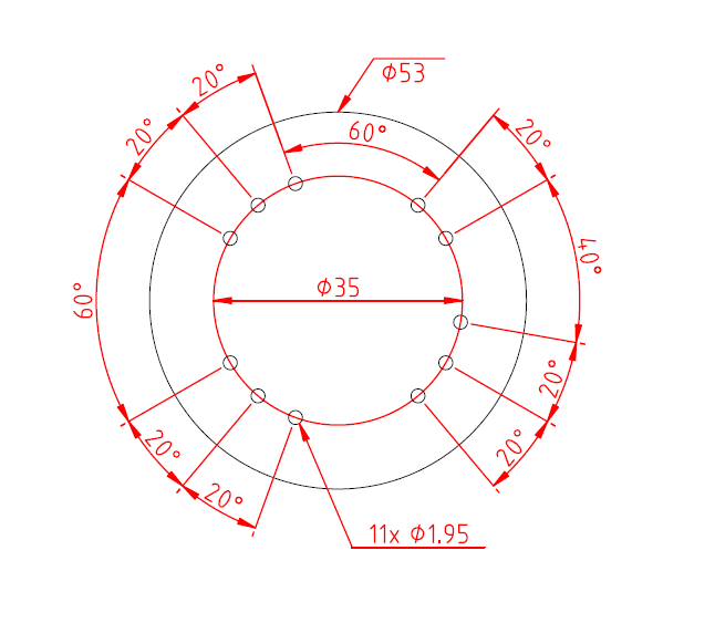
CAD file: Footprint.dxf
Driving circuit
Important
Warning: Nixie tubes require high voltage which can be lethal. Please be careful and never touch the high voltage contacts with a bare finger.
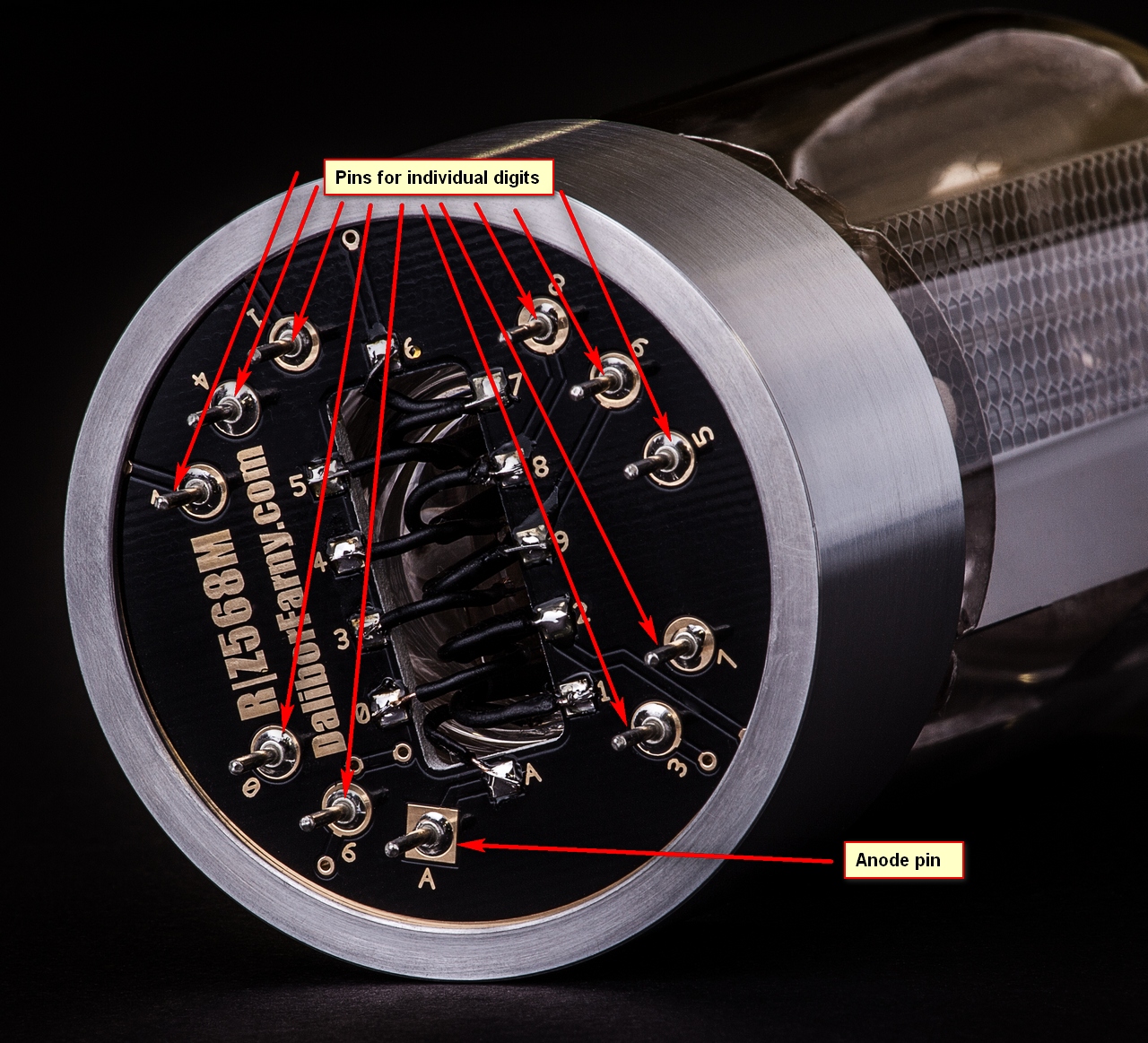
To drive a nixie tube, you first need to connect its anode pin to 170 VDC via an anode resistor (8200Ω recommended value). To light up the desired digit, it is necessary to bring its pin to the ground (0 VDC), this can be done in many ways – connecting by wire directly, using discrete transistors (refer to [1]), or chips which are designed for this purpose (e.g. Microchip HV5622).
High voltage power supply
As a source of high voltage, I recommend a step-up converter that creates 170VDC from low voltage (typically 5-12VDC). As an example, I can name a few modules I have experience with, they are all very well designed, efficient and reliable.
1364 – SmartNixie HVPS-H by Taylor Electronics – small high voltage power supply, variable high voltage output (150-200 VDC). It can drive up to 6 of our R|Z568M nixie tubes. Several external parts are needed to set it up.
Simple way
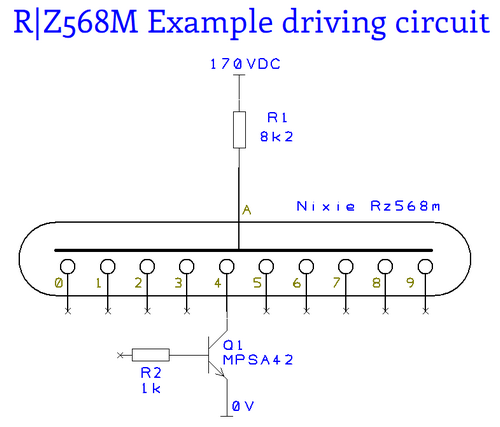
This is a simple driving circuit using a discrete high voltage transistor MPSA42. To light up a digit, connect the base of the transistor to 5V. To turn it off, leave the base at 0V. There is just one transistor shown in the circuit (for digit “4”), each digit must have a transistor connected in a similar way – there will be 10 transistors in total.
The advantage of this circuit is its simplicity and low demands on space on the PCB. The disadvantage is that when driving the nixie tube this way, the individual digits have small differences in brightness (intensity of the light per square unit of the cathode). This also means that the sputtering on the individual digits have different rates which can cause faster development of cathode poisoning on rarely used digits. If you like to do it properly, I recommend the “Proper way” circuit.
The maximum heat dissipated on the anode resistor is around 300 mW, we recommend using resistors in the 2512 package which is usually rated for 1000 mW.
Proper way
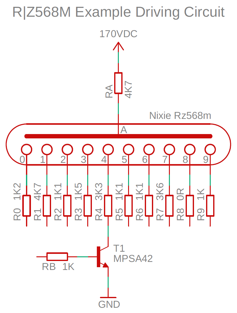
This is a driving circuit using a discrete high voltage transistor MPSA42 and cathode resistors. These resistors slightly reduce the effect of cathode poisoning by equalizing the current of individual digits. To light up a digit, connect the base of the transistor to 5V. To turn it off, leave the base at 0V. There is just one transistor shown in the circuit (for digit “4”). Each digit must have a transistor connected in a similar way – there will be 10 transistors in total.
The maximum heat dissipated on the resistors is around 200 mW, we recommend using resistors in the 1206 package which is usually rated for 250 mW.
The anode resistor is 4k7 Ω.
Cathode resistors values:
| Digit | Resistor Value |
|---|---|
| 0 | 1k2 Ω |
| 1 | 4k7 Ω |
| 2 | 1k1 Ω |
| 3 | 1k5 Ω |
| 4 | 3k3 Ω |
| 5 | 1k1 Ω |
| 6 | 1k1 Ω |
| 7 | 3k6 Ω |
| 8 | 0R Ω |
| 9 | 1k Ω |
Further reading about driving nixie tubes:
Driving Nixie With Discrete Transistors
Driving Nixie Tubes by Threeneuron
Cathode poisoning prevention routine
Nixie tubes tend to develop a phenomenon called “cathode poisoning” on digits that are not in regular use. To make sure the digits in your clock stay in good condition, all of them need to be exercised regularly. This is done by running a “cathode poisoning prevention routine” regularly.
When writing your own code for a clock (or any other display with our R|Z568M nixie tubes), please use ratio 60s: 0.2s. For every 60 seconds when the tube is on (whatever digit), exercise every other digit for 0.2s. For instance, if you let your display run for 10 minutes (600 seconds) on digit “1” (this is the case of the leftmost tube in a typical clock), you need to run a routine that will let each other digit glow for 2 seconds (60*10: 0.2*10).
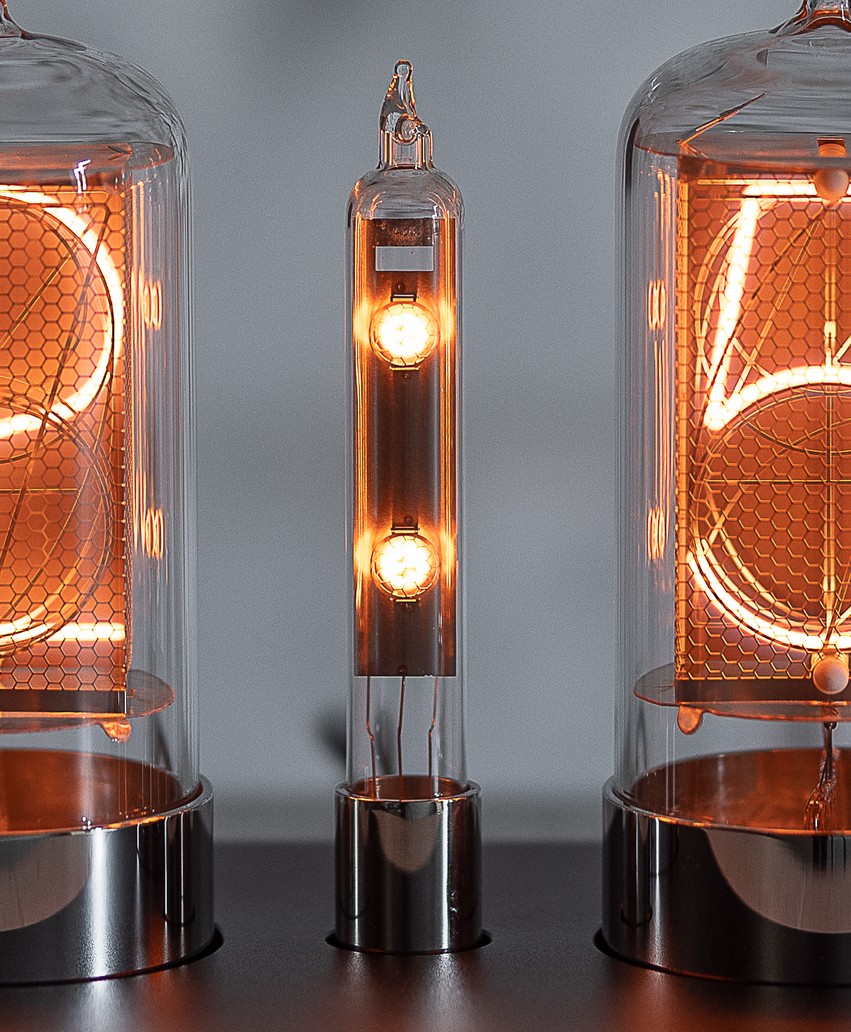
R Colon tube
Technical data
PDF Drawing of the socket: Socket drawing
Socket 3D model to view/download: https://a360.co/3eFYJhC
Driving circuit
Important
Nixie tubes require high voltage which can be lethal. Please be careful and never touch the high-voltage contacts with bare fingers.
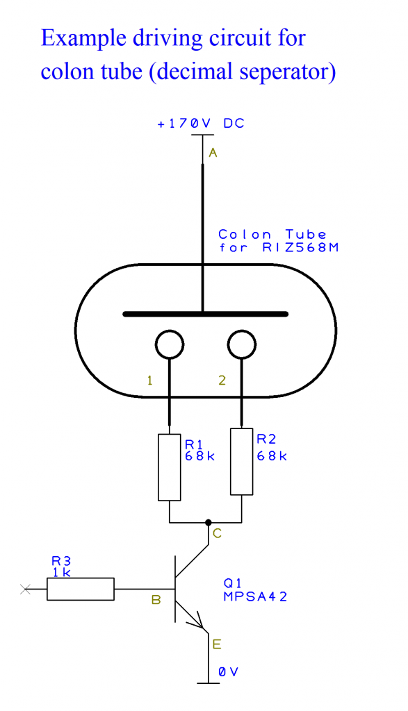
To drive a decimal separator (colon-) tube, you must first connect its anode pin to 170 VDC. Compared to a normal nixie-tube, the decimal separator needs a cathode resistor on every cathode (68,000 Ω or 68 kΩ recommended value). To light up the two dots, it is necessary to short the cathode resistors to ground (0 VDC, please also refer to Driving-Circuit for the R Nixie tube).
This is a simple driving circuit using a discrete high-voltage transistor MPSA42. To light up the separator, connect the base of the transistor to 3V to 12V. To turn it off, connect the Base to 0V or leave it floating. In this circuit, the two dots are lit up together, but it is also possible to drive them separately.